VULKAN Sets the Benchmark
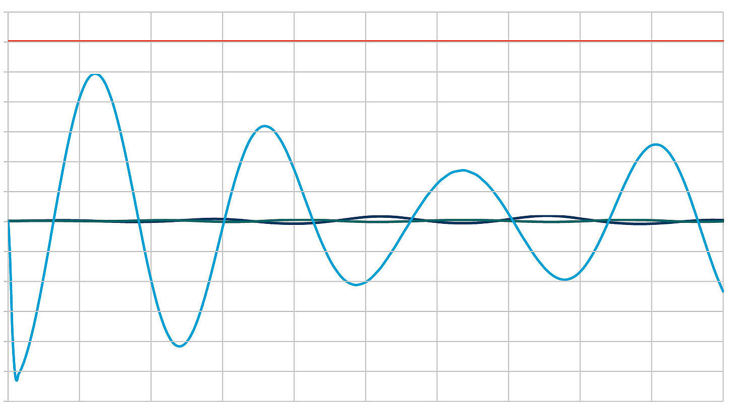
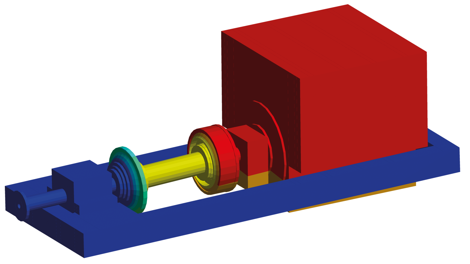
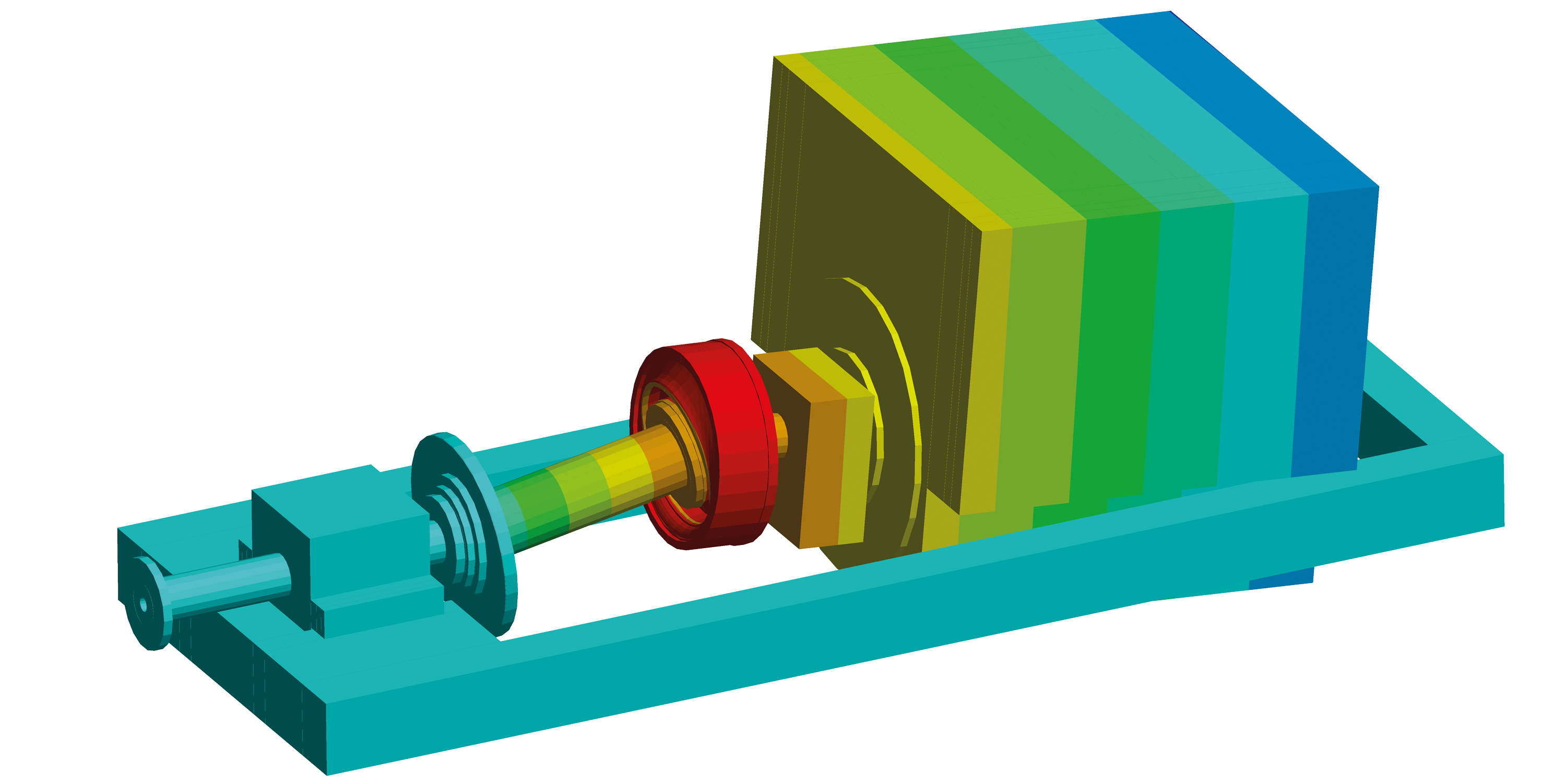
VULKAN sets the benchmark in detailed time-domain transient shock analysis, employing comprehensive force-deflection characterization of resilient mounts and precision modeling of coupling components, enabling evaluation of peak von Mises stresses in metallic parts and maximum strains in elastomer elements. Our sophisticated, integrated system simulations using state-of-the-art software rigorously assess shock-induced displacements, residual accelerations and structural integrity – ensuring naval propulsion systems deliver uncompromised reliability under the harshest operational conditions.
Ensuring Shock-Qualified Performance
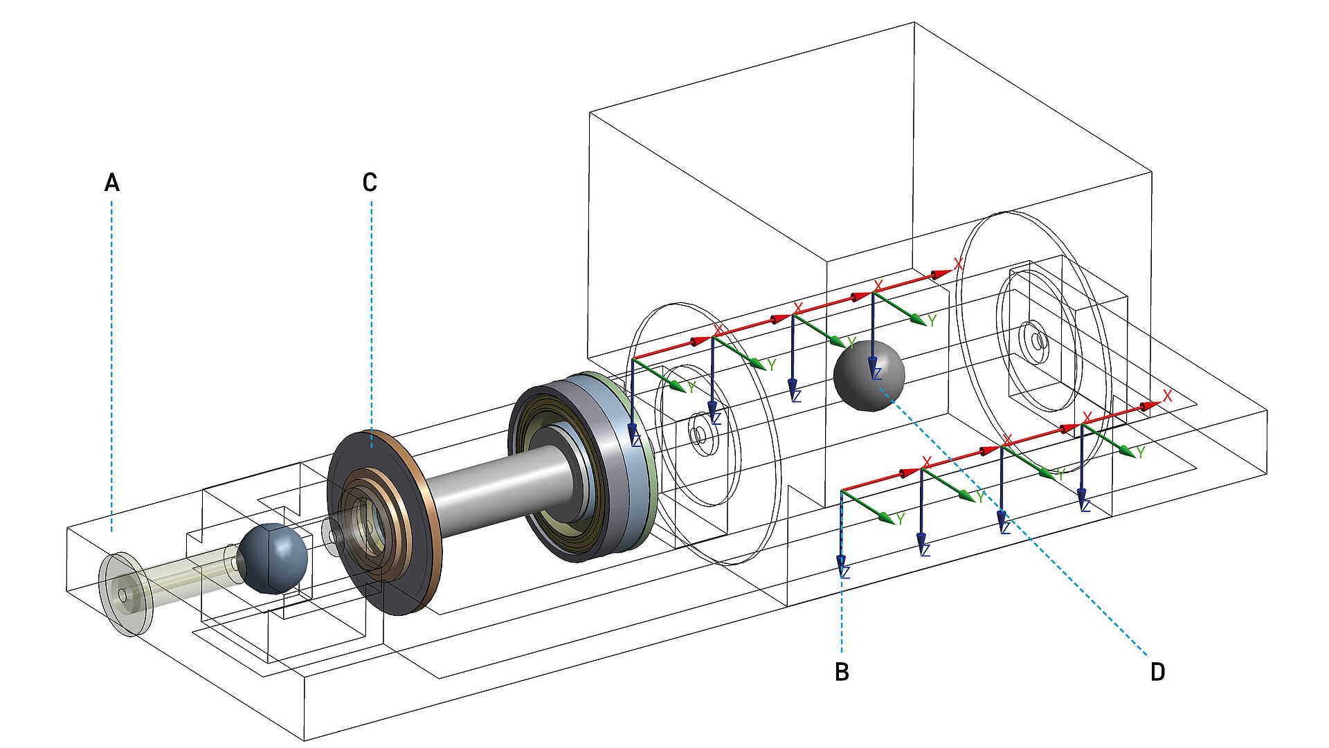
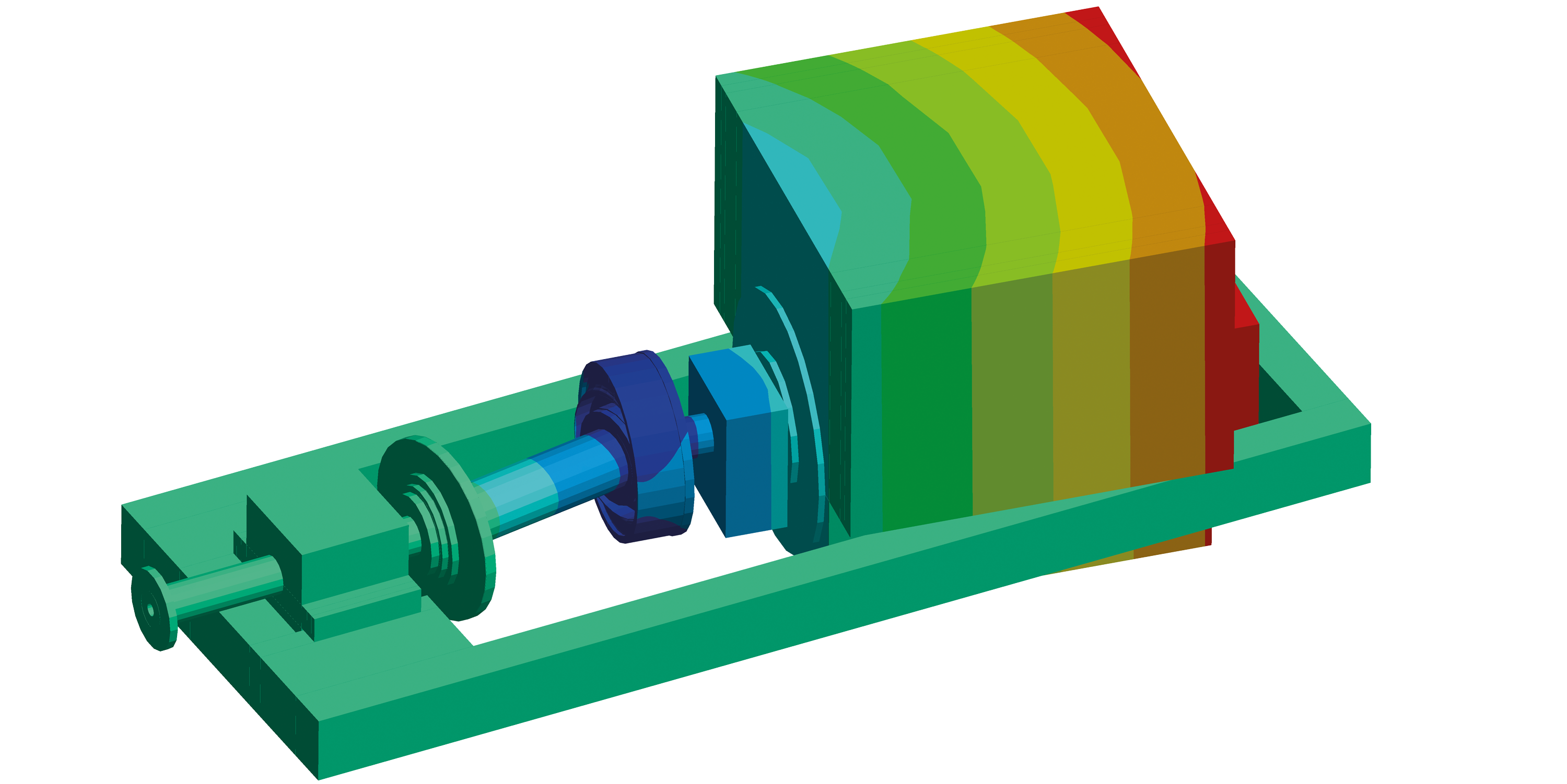
VULKAN’s capability to conduct full-system shock simulations in all critical directions and direction combinations (longitudinal, lateral, vertical, and Biaxial), means that we can realistically predict equipment displacements, structural loads and component behavior under naval shock conditions. This allows us to determine shock qualification of mounts and couplings, validate system integrity and provide clear guidance for safe integration of couplings and mounts into the overall propulsion plant. By combining component-level characterization with system-level modeling, our expertise transforms complex simulation data into practical design decisions. This approach enables VULKAN to gain the insights needed to fine-tune coupling–mount interaction and ensure that propulsion systems work as intended under shock. At the same time, it provides shipyards, naval architects and system integrators with validated information to reduce technical risk. Together, these capabilities secure compliance with naval shock standards and reliable performance across the vessel’s operational profile.
Shock Mount
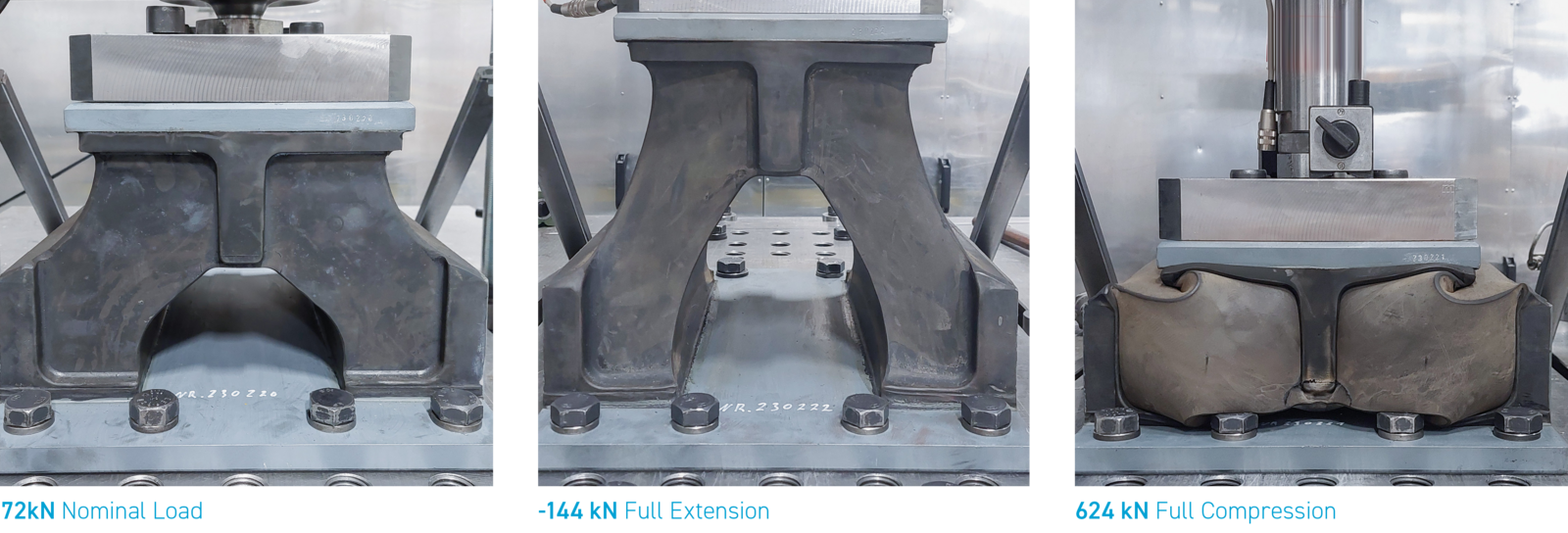
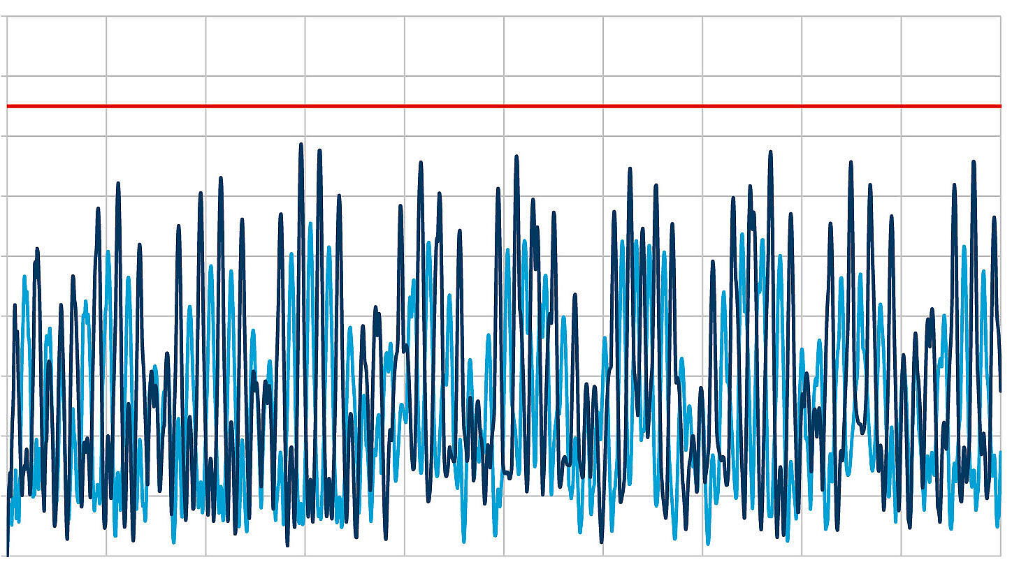
An underwater explosion (UNDEX) close to the vessel leads to extremely high acceleration levels of the ship’s hull in a very short period of time.
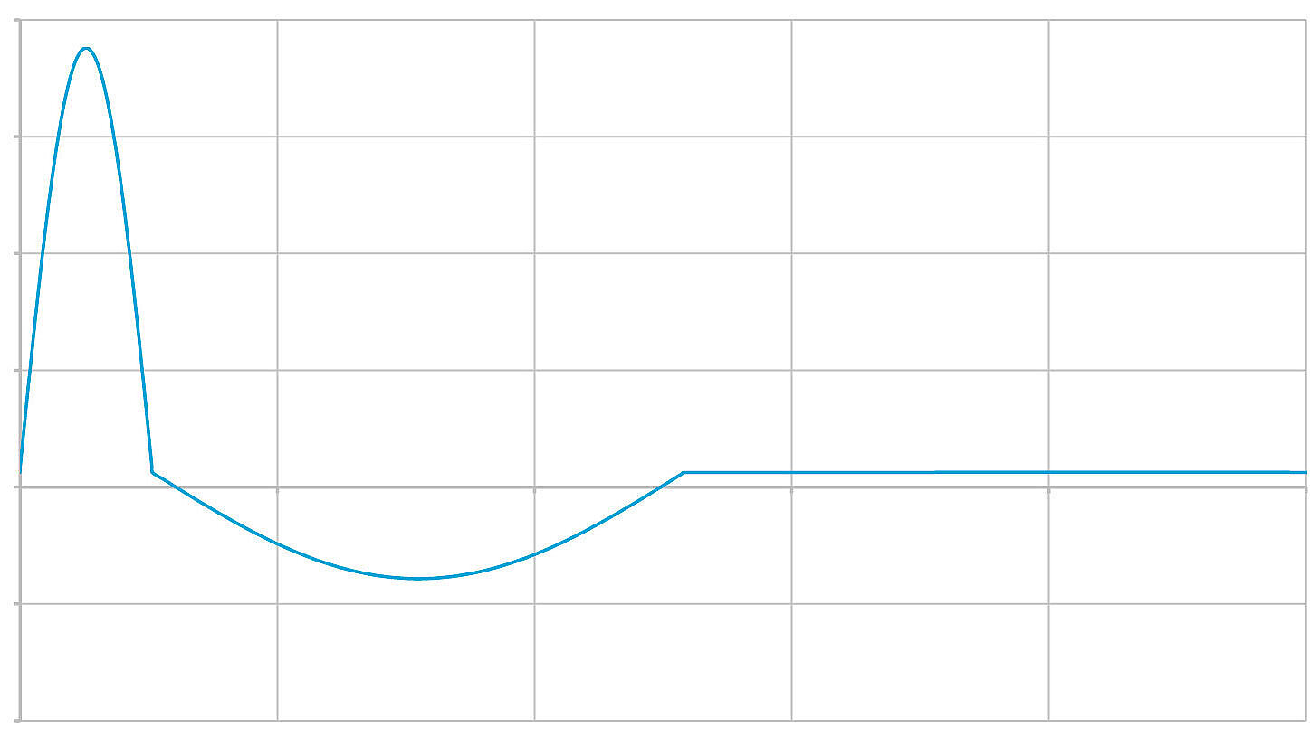
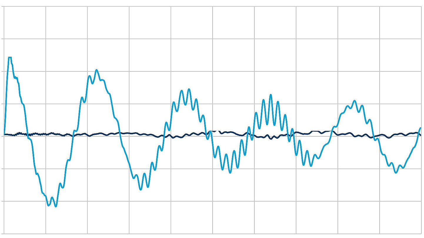
In order to protect equipment and components against these high acceleration levels, high-deflection shock mounts can be used. The main difference with other resilient mounts is that shock mounts can handle high deflections which occur during a shock event. The shock mount absorbs the displacement of the hull and protects the equipment above the mount. After the initial compression of the mount, the shock mount returns to its original shape in a much slower pace than the compression during the shock event.
As the equipment experiences mainly the slow pace extension of the shock mount, the acceleration levels on the equipment are much lower. By applying shock mounts it’s possible to use regular shipboard equipment onboard navy vessels.
Due to the large amount of rubber, the acoustic isolation performance of a shock mount is outstanding. Therefore, shock mounts are also frequently chosen for high structure borne noise isolation onboard yachts and research vessels. Another advantage of rubber is that it provides damping to the resilient mounted setup of the equipment. This limits vibration amplitudes on the equipment and displacements during seaway motions.